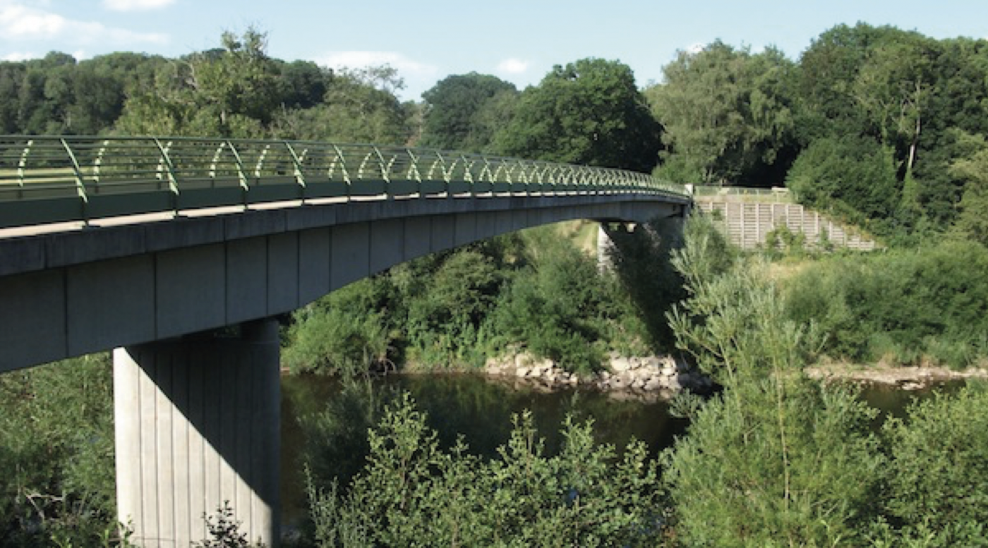
The Highley and Alveley footbridge is a replacement bridge crossing over the River Severn between Highley and Alveley in Shropshire. Arup designed the bridge for Mowlem Construction Ltd with Ivor King Piling Ltd installing the piles. The bridge is a three span continuous reinforced concrete footbridge and was completed in 2006. The main central span is approximately 48m with side spans each of 19.5m, skewed at 30° and full height abutments. Piers and abutments are located on the banks of the river.
The stratigraphy generally comprised Made Ground (mainly colliery spoil) overlying alluvial sands, silts and clays overlying a thin layer of River Terrace Deposits of clayey sandy gravel. Bedrock comprised interbedded mudstones and siltstones of the Upper Coal Measures. Both piers and the Alveley bank abutment (shown above) are founded on steel piles. However, the Highley abutment is founded on landslipped material which may potentially move, so in order not to attract loads from this material, it was founded at shallow depth.
Design and Construction
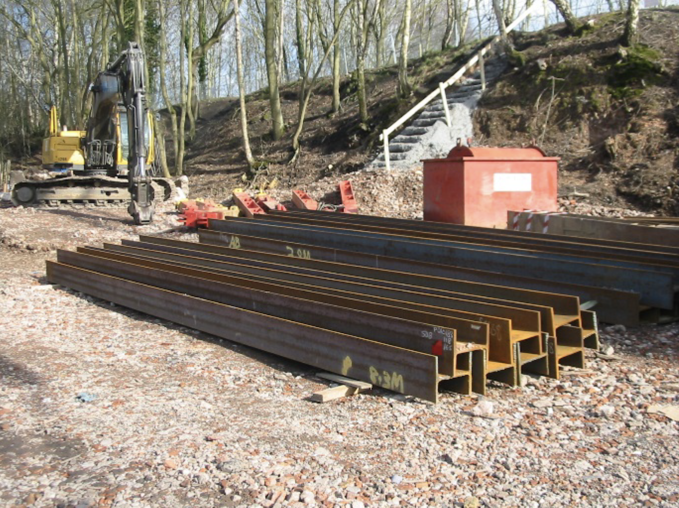
A total of 40 vertical steel H-piles (305 mm x 305 mm UBP, 110 kg/m to 240 kg/m) between 6.5 m and 12 m long were driven from existing ground level through the superficial deposits into the underlying bedrock. Determination of vertical pile capacity was undertaken in accordance with the Steel Bearing Piles Guide P156 produced by the Steel Construction Institute (SCI) (1997) and the publication entitled “Piled foundations in weak rock” produced by CIRIA (1999).
This method was validated for H-piles using back analysis, which took into account the method of installation and any strength reduction of the rocks encountered during driving.
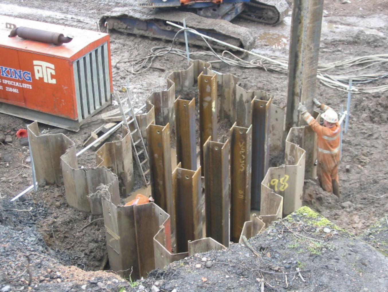
Individual pile loads ranged from 400 kN to 1125 kN. Using the two preliminary static load tests and a SPTbased approach for shaft and base capacity, a minimum toe penetration of 4.5 m into bedrock was required. The static load tests also showed that, provided a minimum factor of safety of 1.5 on the total applied load on an individual pile could be demonstrated by CAPWAP testing, pile movements under the total applied load would be within acceptable values. The bridge site has poor accessibility and the piling contractor selected an 8.5 tonne Dawson HPH4500 hydraulic piling hammer with a 3500 kg hammer dropping through a 1 m height. In order to judge that the ultimate pile capacity could expect to be reached by the selected driving hammer, the nomogram for the Hiley formula published in SCI P156 (1997) was used. The nomogram showed that the selected piles with the selected hammer could achieve an ultimate resistance, without compromising the manufacturer’s warranty regarding the effects of hard driving (i.e. not more than 10 blows per 25 mm at pile founding level).
Steel Piling Group, C/O SCI, Unit 2, The E Centre, Bracknell, RG12 1NF, UK
E: info@steelpilinggroup.org
![]()
© Copyright 2025 Steel Piling Group
Terms & Conditions | Privacy Policy