Until the advent of the Eurocodes, geotechnical design of retaining walls was carried out to BS 8002:1994, with additional reference to CIRIA 104 ‘Design of retaining walls embedded in stiff clay’.13 An updated CIRIA Guide C580 ‘Embedded retaining walls – guidance for economic design’ was published in 2003. The design approach methodology contained in CIRIA C580 was based on the draft Eurocode 7 in development at the time. Whilst the concepts are similar, the actual design approaches set out in the final Eurocode 7, published in 2004, differ in the detail.
In 2015 BS 8002 was published providing designers with the guidance they need to implement the requirements of Eurocode 7 with regards to gravity, semi-gravity and embedded retaining walls. The standard also gives further details on how retaining structures should be designed according to limit state principles and provides information missing from Eurocode 7 but of importance to UK practice. At the same time, advances in retaining wall technology over the past 20 years are reflected in the fully revised text.
Most recently in 2017, a new guide CIRIA C760 Guidance on embedded retaining wall design was published. This guide is intended for use in the design of sheet pile, king post, contiguous bored pile, secant bored pile and diaphragm walls. It supersedes CIRIA guide C580. This new guide is compatible with the relevant Eurocodes and its range of application has been extended to include soft clays and weak rocks.
Structural design of steel sheet pile retaining walls is carried out in accordance with Eurocode 3 Design of Steel Structures Part 5 Piling, replacing BS 5950 ‘Structural Use of Steelwork in Building’.
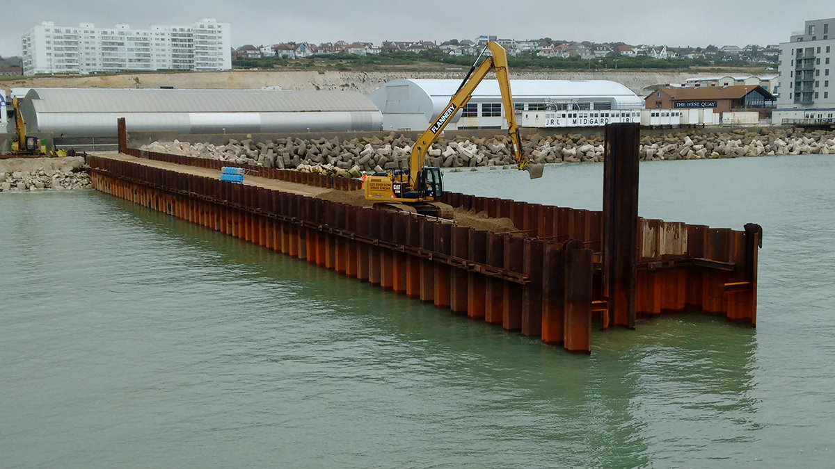
The design guidance documents mentioned above are primarily for land based structures. However, maritime structures form an extensive market where steel piling solutions are most attractive. Hence for specific design requirements for maritime structures (quay walls, cofferdams etc) reference shall be made to BS 6349-2.
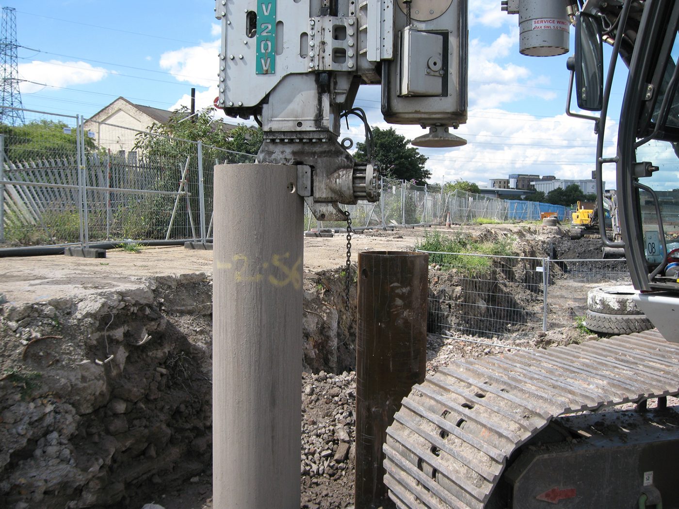
Sheet-piled walls
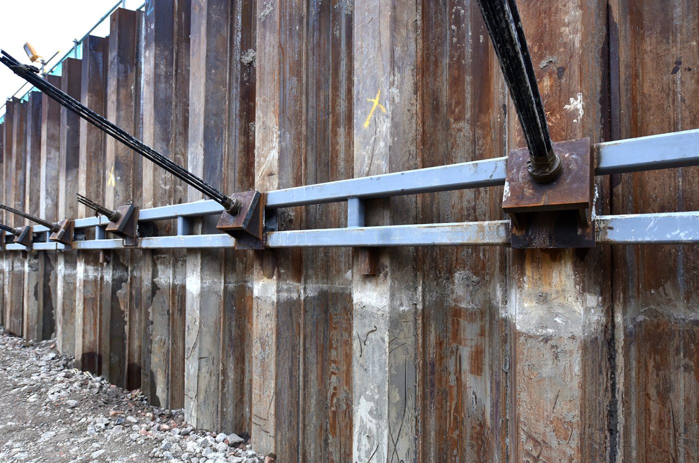
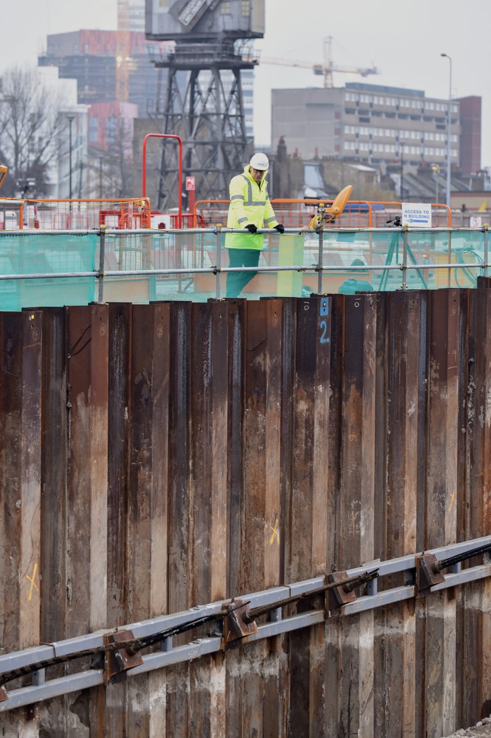
Steel sheet piles are the most widely used embedded retaining wall elements in quays and jetties. They are relatively light and easy to handle, they can be supplied in long lengths and can be extended and cut without undue difficulty.
NOTE 1 Guidance on the installation of steel sheet piles is given in BS EN 12063, and this includes guidance on welded joints and many other issues.
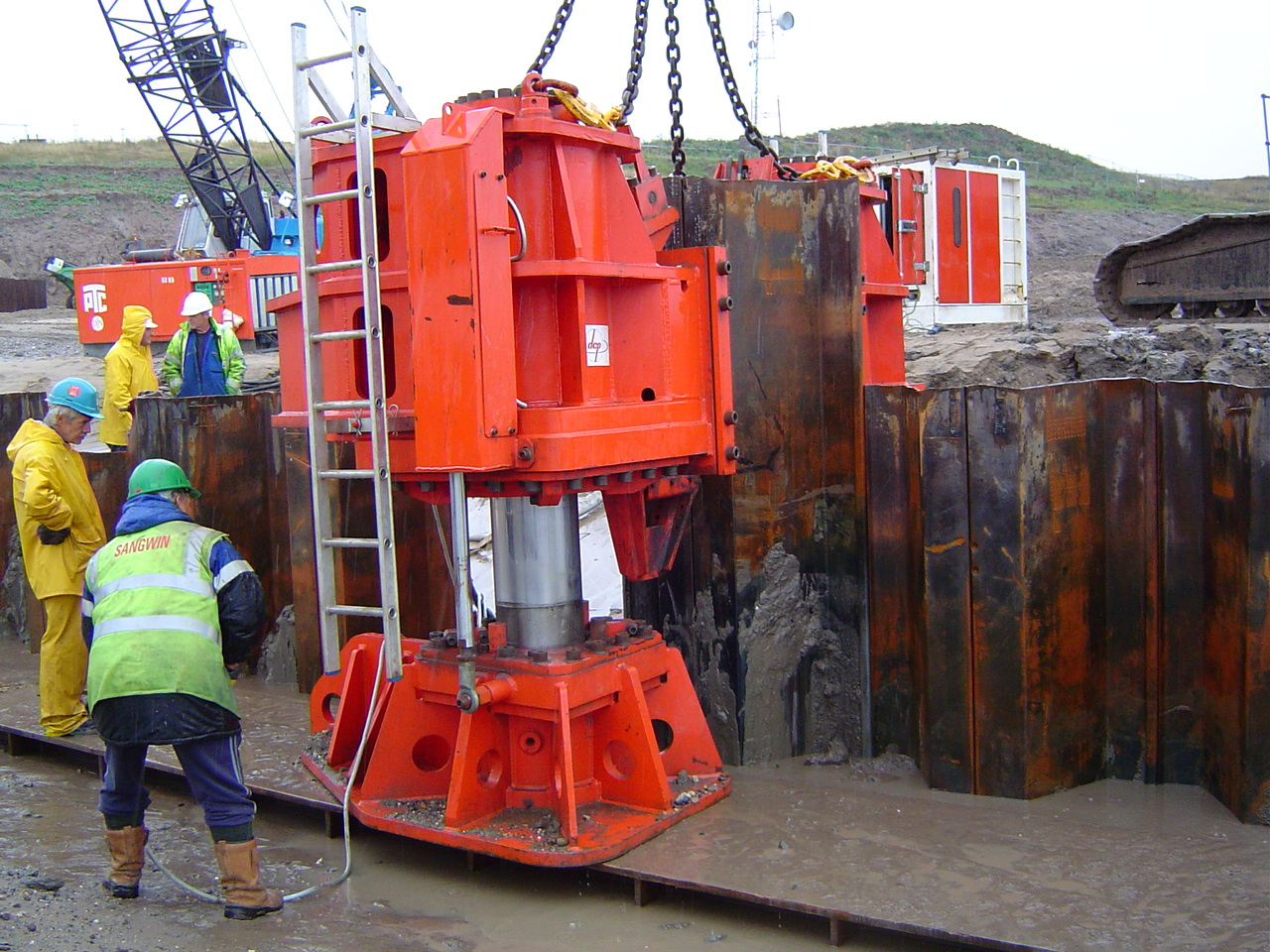
This type of pile can be driven to considerable depth with low displacement in a wide range of ground conditions and into weathered rock. Where hard driving is encountered, the pile section required might exceed the section needed to resist bending. This should be taken into account in assessing the reduction of moments. With various forms of pre-treatment, steel sheet piles may also be installed in solid rock, in a trench backfilled with concrete, by pre-splitting the rock or by the use of toe dowels as detailed in BS EN 12063.
The interlocks are generally tighter than for timber or concrete piles.
The principal disadvantage of steel sheet piles is corrosion, however this can easily be allowed for in design, see the durability section for more detail.
Some types of floating fenders can cause abrasion of steel sheet piles or their protective coatings, and this should be taken into account in selecting the form of fendering to be adopted.
The most commonly used interlocking pile sections for steel embedded retaining walls are the U- and Z- types. Several combined wall sections are also available, usually comprising H-piles, box piles or tubular piles with either interlocking sheet pile elements or separate interlocks.
Additional bending resistance can be achieved, where the piles are to be driven to a predetermined level, by welding reinforcing plates to the pile flanges in zones of maximum bending moment.
NOTE 2 Examples of interlocking steel pile sections and combinations of elements suitable for use in embedded retaining walls are given in BS EN 1993-5.
Construction tolerances should generally be in accordance with 8.13 and BS EN 12063.
NOTE 3 The ICE specification for piling and embedded retaining walls gives further guidance on tolerance
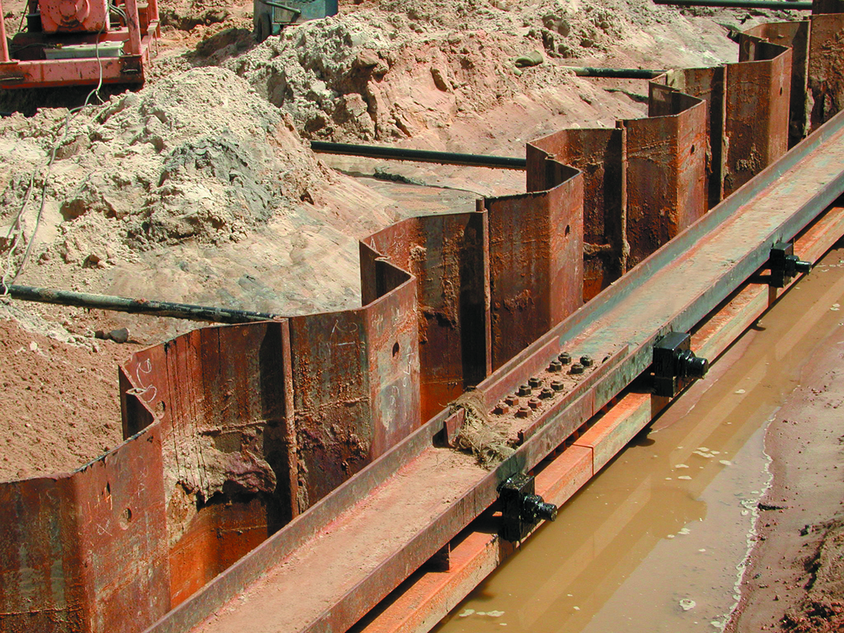
Soldier piles and sheeting
Embedded retaining walls constructed using soldier piles and horizontal sheeting are not widely used in maritime works, owing to the high cost of the diving work involved and the tight constructional tolerances required to avoid loss of backfill. However, this type of wall might be a suitable way to provide a deeper retaining face outside an existing wall, where minimum interference with port operations is essential.
The piles may be of steel or concrete, either precast or in situ: pre-stressing is normally advisable to reduce weight and improve durability. Preformed piles may be installed, by driving or placing in a preformed hole, in any seabed material, but might require an excessive penetration in soft clays and silts. In-situ concrete piles are subject to the usual limitations of bored piles.
The penetration of the piles into the seabed should be calculated to take into account the consequences of failure of the ground support.
The heads of all piles should be temporarily supported until the capping is cast and the anchors installed.
The sheeting in quay walls of this type is usually of precast concrete planks. The sheeting should be secured to the soldier piles to prevent differential movement and consequent loss of material. Figure 1 shows an example of such a construction. Care should be taken to provide appropriately sealed joints to prevent loss of material.
Construction tolerances for soldier piles should be in accordance with 8.13.
NOTE The ICE specification for piling and embedded retaining walls gives further guidance on tolerances.
Combined steel sheet piles
In combined steel sheet-piled walls in which the intermediate sheeting is required to contribute to the bending resistance, welding of the interlocks will in many cases be required. If the modulus of the H-section, box or tube far exceeds that of the intermediate sheeting, it may be assumed that all horizontal actions are transmitted to the large modulus elements and no welding of interlocks is then required. The intermediate sheeting, in the latter case, may be of lighter section than would be necessary if it were designed to span vertically. Soldier-piled walls are also designed assuming that all horizontal actions are transmitted to the soldier piles.
Actions and effects of actions on embedded retaining walls
The actions on a retaining wall are summarized in BS EN 1997-1:2004, 2.4.2 and some or all of these will be appropriate to the design of a specific structure.
The stresses obtained by analysis should be in accordance with BS EN 1992, BS EN 1993, BS EN 1995 or BS EN 1997 as appropriate to the material under consideration. Crack widths (see 4.4.2.3) should be calculated for the serviceability limit state.
These stresses in steel and timber elements should be based on the wall section at the end of the design life.
The maximum bending moment in embedded retaining walls does not usually coincide with the most severe zone of corrosion, and this should be taken into account in the analysis of steel sheet-piled walls.
The geotechnical parameters should be established in accordance with the requirements of BS EN 1997-1 through an appropriate geotechnical investigation. The partial factors to be applied to actions, and the method to be used for combining actions, should be in accordance with Clause 5 of the present standard. The partial factors applied to the geotechnical parameters should be taken from BS EN 1997-1.
The driving of steel sheet and timber piles should be in accordance with BS EN 12063.
Where support fluid is used in the excavation of in-situ concrete embedded retaining walls, the permissible bond stress of deformed steel reinforcement might have to be reduced.
Further guidance is given in the ICE specification for piling and embedded retaining walls.
Walings should be designed in accordance with BS EN 1993-5.
Cellular sheet-piled structures
Cellular sheet-piled structures consist of cells formed by interlocking straight-web steel sheet piles, driven or placed with their tops above water level. The cells are filled with granular material. The superstructure may be a solid in-situ concrete capping, or a reinforced concrete edge retaining wall which is backfilled and the top surfaced.
Cellular sheet-piled walls are gravity structures that function partly as cantilever walls where pile embedment can be achieved.
Sheet-piled cells may be founded on soft rock, granular material or very stiff clay. Where soft clays exist, they should be removed before filling the cells. This soft material should be dredged prior to cell construction at sites where the soft material layer is very thick, to avoid causing compression of the cells. Cellular structures may be used for both quay walls and jetties. They use less steel than double-wall sheet wall structures because the steel resists the lateral soil actions in hoop tension rather than bending, and walings, tie rods and bulkheads are generally not required.
This type of structure is particularly liable to damage by wave action during construction without the provision of adequate robust temporary works. This form of structure possesses little resistance to horizontal actions before the internal filling is completed.
Read more about Steel Bearing Piling Design
Case Studies
A selection of our work
Steel Piling Group, C/O SCI, Unit 2, The E Centre, Bracknell, RG12 1NF, UK
E: info@steelpilinggroup.org
![]()
© Copyright 2025 Steel Piling Group
Terms & Conditions | Privacy Policy