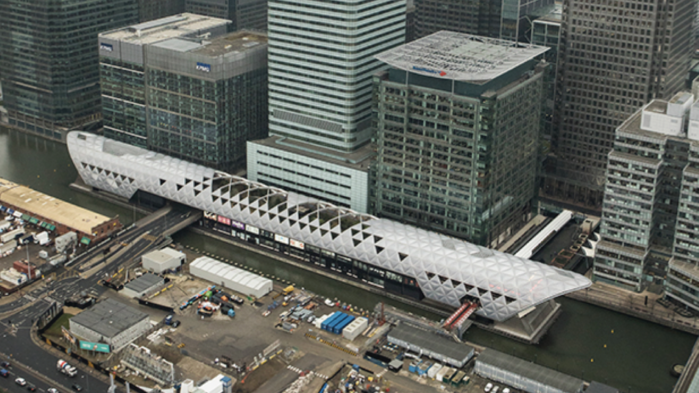
Completed in 2015, the Canary Wharf Crossrail Station in East London was the first Elizabeth Line station built. The piles and concrete structure were designed by Arup for Canary Wharf Contractors Ltd and constructed by Expanded Ltd. The station structure is 260m long, between 25m and 30m wide and was built within a dock. The formation level of the station box is approximately 18m below the dock bed level and the dock is 9m deep. The station was constructed from dock bed by top-down construction within a cofferdam which was formed of a tiedback retaining wall on three sides and utilised the existing basement structures to the south to provide water cutoff. The retaining wall was a composite steel/concrete piled wall formed in part using the Japanese Giken silent piling system. This is the largest project in the UK to use the Giken technique over water.
The downward geological sequence generally comprised dock sediment, made ground, River Terrace Deposits, Lambeth Group clays, Upnor Formation, Thanet Sands and Chalk. The hydrogeology of Canary Wharf includes the upper aquifer which lies within the River Terrace Deposits and lower aquifer within the Lambeth Group sands, Thanet Sand and the underlying Chalk. They are separated by an aquiclude that is predominately formed of lowpermeability clays of the Lambeth Group.
Design and Construction
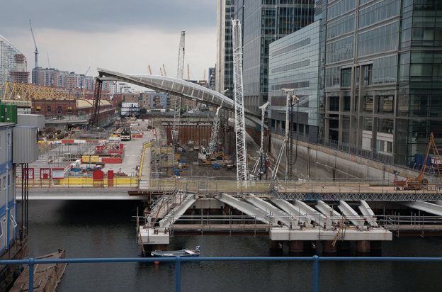
The east, north and west retaining walls were formed using 310 interlocking tubular steel piles installed over water using the silent piling technique. It uses a combination of augering and hydraulic push-in force to advance the piles. The geometries of the tubular steel piles were 1219 mm external diameter, typically 14 mm wall thickness and 18.5 m long. The steel tubular piles were interlocked, using grouted Giken’s P-P clutches, to prevent water ingress into the cofferdam. Conventional bored piles were then constructed through the toe of the tubular piles to form a composite wall. This retaining wall was tied back to 120 single steel tubular anchor piles, located behind the wall at 3m centres.
The design of the innovative retaining wall for lateral stability was undertaken to Eurocodes and CIRIA C580. The cofferdam was modelled using the two-dimensional finite-element Plaxis program. The use of finite-element analysis allowed the modelling of asymmetric loading, or ‘sway’, from the tiedback cofferdam towards the existing buildings to the south. This was due to the out-of-balance force caused by retaining dock water acting on only one side of the station cofferdam during construction.
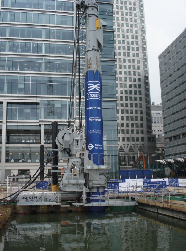
In 2009, two specially adapted Giken Supercrush SCP300 silent piling rigs were shipped directly from Japan. These installed the steel tubular interlocking piles using a combination of augering and hydraulic push-in force to advance the piles. The maximum observed vertical push-in force was between 1500 and 1800kN; up to 9kNm of auger torque was also recorded. The construction tolerance sachieved during the works were principally ±26mm in position and 1:150 verticality.
An adequate hydraulic seal into the Lambeth Group clay was fundamental for the water cut-off to work and as a result the last 0.5m of the steel pile was pushed in without augering. The average production rate of each Giken piling rig was three tubular piles per day up to a maximum of four, assuming no head room or other restrictions to working conditions.
The project won the 2011 Ground Engineering award for technical excellence due to innovation in its design and construction techniques.
Steel Piling Group, C/O SCI, Unit 2, The E Centre, Bracknell, RG12 1NF, UK
E: info@steelpilinggroup.org
![]()
© Copyright 2025 Steel Piling Group
Terms & Conditions | Privacy Policy